


Class 12
NCERT
Chapter 1: Electric Charges and Fields
47 questions
Chapter 2: Electrostatic Potential and Capacitance
46 questions
Chapter 3: Current Electricity
33 questions
Chapter 4: Moving Charges and Magnetism
41 questions
Chapter 5: Magnetism and Matter
36 questions
Chapter 6: Electromagnetic Induction
28 questions
Chapter 7: Alternating Current
37 questions
(a) Determine the source frequency which drives the circuit in resonance.
(b) Obtain the impedance of the circuit and the amplitude of current at the resonating frequency.
(c) Determine the rms potential drops across the three elements of the circuit. Show that the potential drop across the LC combination is zero at the resonating frequency.
(b) What is the natural frequency of the
circuit?
(c) At what time is the energy stored
(i) completely electrical (i.e., stored in the capacitor)?
(ii) completely magnetic (i.e. stored in the inductor)?
(d) At what times is the total energy shared
equally between the inductor and the capacitor?
(e) If a resistor is inserted in the circuit,
how much energy is eventually dissipated as heat?
Chapter 8: Electromagnetic Waves
20 questions
Solving time: 4 mins
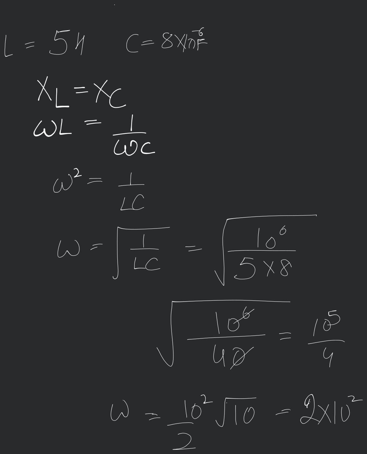
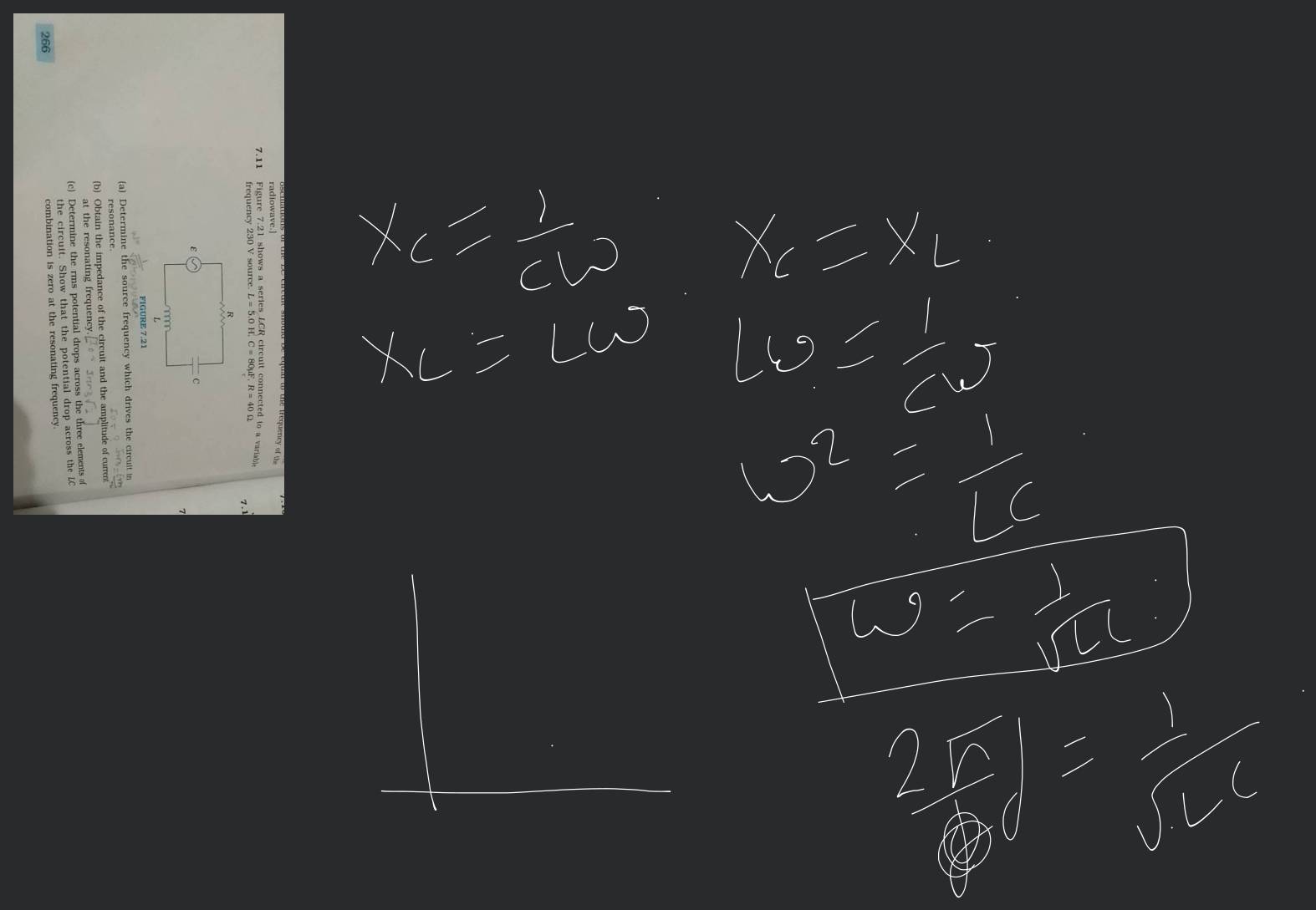
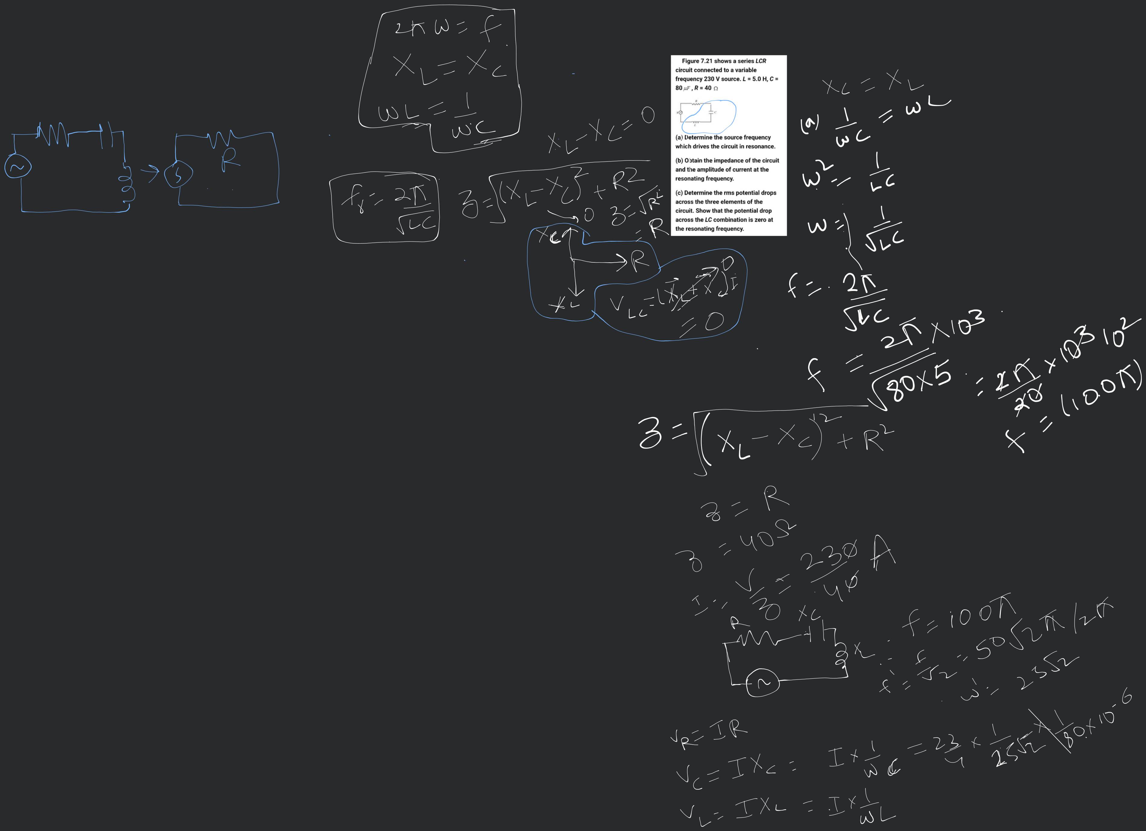
Figure shows a series LCR circuit connected to a variable frequency 230 V source. L = 5.0 H, C = 80 μF, R = 40Ω.
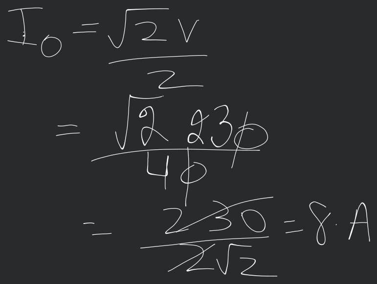
(a) Determine the source frequency which drives the circuit in resonance.
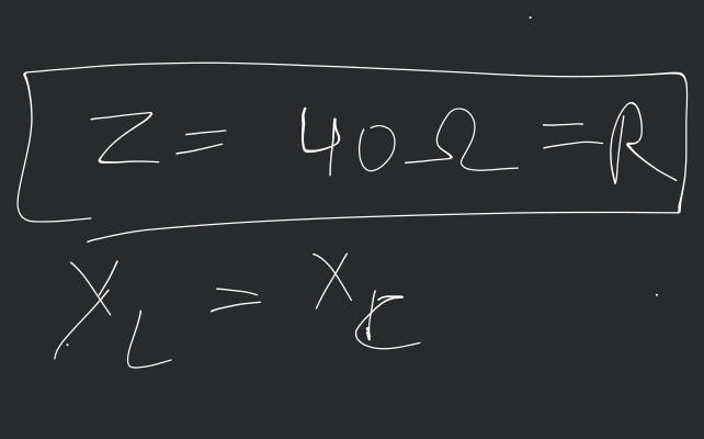
(b) Obtain the impedance of the circuit and the amplitude of current at the resonating frequency.
(c) Determine the rms potential drops across the three elements of the circuit. Show that the potential drop across the LC combination is zero at the resonating frequency.

Views: 6,660 students
(a) Determine the source frequency which drives the circuit in resonance.
(b) Obtain the impedance of the circuit and the amplitude of current at the resonating frequency.
(c) Determine the rms potential drops across the three elements of the circuit. Show that the potential drop across the LC combination is zero at the resonating frequency.
 Text solution
 Verified
(b)
At resonance,
The peak voltage,
(c)
Potential drop across inductor,
Potential drop across capacitor,
Potential drop across resistor,
Potential drop across the LC combination
= (-)
at resonance =
Filo tutor solutions (5)
Learn from their 1-to-1 discussion with Filo tutors.
Uploaded on: 11/9/2023
Connect instantly with this tutor
Connect now
Taught by

Total classes on Filo by this tutor - 5,427
Teaches : Physics, Mathematics, English
Connect instantly with this tutor
Notes from this class (4 pages)

Uploaded on: 3/4/2023
Connect instantly with this tutor
Connect now
Taught by

Total classes on Filo by this tutor - 6,171
Teaches : Physics, Biology, Organic Chemistry
Connect instantly with this tutor
Notes from this class (1 pages)
Uploaded on: 3/7/2023
Connect instantly with this tutor
Connect now
Taught by

Total classes on Filo by this tutor - 139
Teaches : Physics, Mathematics
Connect instantly with this tutor
Notes from this class (1 pages)


Practice more questions from Physics Part-I (NCERT)
(a) Determine the source frequency which drives the circuit in resonance.
(b) Obtain the impedance of the circuit and the amplitude of current at the resonating frequency.
(c) Determine the rms potential drops across the three elements of the circuit. Show that the potential drop across the LC combination is zero at the resonating frequency.
(b) What is the natural frequency of the
circuit?
(c) At what time is the energy stored
(i) completely electrical (i.e., stored in the capacitor)?
(ii) completely magnetic (i.e. stored in the inductor)?
(d) At what times is the total energy shared
equally between the inductor and the capacitor?
(e) If a resistor is inserted in the circuit,
how much energy is eventually dissipated as heat?
Practice questions from Physics Part-I (NCERT)
Views: 5,613
(b) Obtain the rms values of potential drops across each element.
(c) What is the average power transferred to
(d) What is the average power transferred to
the capacitor?
(e) What is the total average power absorbed by the circuit? [Average implies average value over one cycle.]
Views: 6,115
i. When capacitor is air filled.
ii. When capacitor is mica filled.
Current through resistor is i and voltage across capacitor is V then:
Views: 5,937
Views: 6,102
Practice more questions from Alternating Current
Views: 5,428
(a) the source voltage ,
(b) the nature of the element in box and find its value.
Views: 5,700
(a) The potential difference across and
(b) The impeđance of the circuit
(c) The voltage of AC supply
(d) The phase angle between current and voltage
Practice questions on similar concepts asked by Filo students
Views: 5,037
Views: 5,245
Views: 5,469


Stuck on the question or explanation?
Connect with our Physics tutors online and get step by step solution of this question.


| Question Text | Figure shows a series LCR circuit connected to a variable frequency 230 V source. L = 5.0 H, C = 80 μF, R = 40Ω. (a) Determine the source frequency which drives the circuit in resonance. (b) Obtain the impedance of the circuit and the amplitude of current at the resonating frequency. (c) Determine the rms potential drops across the three elements of the circuit. Show that the potential drop across the LC combination is zero at the resonating frequency. |
| Updated On | Nov 19, 2023 |
| Topic | Alternating Current |
| Subject | Physics |
| Class | Class 12 |
| Answer Type | Text solution:1 Video solution: 5 |
| Upvotes | 581 |
| Avg. Video Duration | 10 min |
